Saturday, 20 October 2012

HOW TO: SET UP A STAGE CYLINDER - PART 3: REGULATORS

In my last 2 articles on stage/decompression cylinders we looked at making the rigging kit (here) and correctly labeling the cylinder (here).  My last looks at setting up the regulators.

Overview
This article is written for stage/decompression cylinders which are worn on the left side of the diver.  This article is also written using Apeks regulators.  This article can be used with other manufactures  regulators however there may be some slight differences.

Setting up
You will need the following:
1. 1st stage (DS4 used in example).
2. 2nd stage (TX40 used in example).
3. SPG (Suunto SM-36 used in example).
4. 6” HP hose.
5. 40” LP hose (depending on first stage used).
6. 6”/15cm of cave line (the stuff from your spool).
7. Lighter.
8. Scissors/knife.
Attach the 1st stage to the cylinder with the HP port facing down.  Then attach the 2nd stage and hose as follows:
1. 40” hose on a fixed turret such as a DS4*.
2. 36” octo/AS hose on a swivel turret such as a DST*. 
(A standard regulator hose is 29” long; too short for the regulator to be looped around the back of the head)
*Refer to manufacturer if unsure.
Then attach the SPG and 6” hose.  The reason a 6” HP hose is used instead of a standard 24” is because it allows better routing.  If the longer hose was used it would either have to be clipped off somewhere, or, if stowed down the cylinder in a similar manor to the regulators, there is a possibility of pulling it out.  The other advantage a 6” hose gives is the gauge is visible without the diver having to use a hand to get to it.

Next take the line and tie a loop approximately 2” long.  As per the boltsnap how to (here), melt the ends with a lighter and flattening them with the base of the lighter.  This will stop the ends from fraying and reduce the risk of the knot coming undone.
Bend the 6” hose back on itself and place the loop over.  It should naturally sit above the ends of the hose.
Notice the hose is protected between the 1st stage and the cylinder valve.
All that’s now left to do is tidy up the 2nd stage hose.  This is routed along the left hand side of the rigging kit with the mouthpiece of the 2nd stage tucked behind the hose keeping it in place, all nice and neat.

Thank you very much for reading.  Hopefully you should now have a stage/decompression cylinder looking something like mine.


The boring bit!
All opinions expressed in my articles are my own and may differ to other instructor’s and agency guidelines; by no means are they wrong and I would not wish to disrepute any of them.  This article is for information only and should not replace proper training.

Safe diving!

Timothy Gort
BSAC, PADI & SDI/TDI diver training
l Mob: 07968148261 l Email: tim@rectotec.co.uk l

Saturday, 6 October 2012

HOW TO: SET UP A STAGE CYLINDER - PART 2: CYLINDER MARKINGS

This article is designed to allow the reader to correctly mark up their stage/decompression cylinder.  Due to only owning a certain quantity of cylinders, I have decided to use masking tape to mark mine however if diving using ‘standard gasses’ all the time then permanent stickers could be used such as those made by Dive Signs. 

Overview
One of the biggest issues concerning any diver (technical or otherwise) using Nitrox is breathing the wrong gas as it will almost certainly lead to oxygen toxicity (as the maximum operating depth (MOD) has been exceeded) leading to death.  To reduce this risk we can do a number of things including analysing the gas upon filling AND re-analysing PRIOR to diving (if the cylinder has been left unattended for a period of time) and ensuring the cylinder is marked up correctly.  The stage/decompression cylinder must:
1. Be free of all unnecessary clutter.
2. Have markings that are clear and easy to read.
3. Have the MOD clearly marked in large numbers on BOTH sides of the cylinders (MOD or m is optional*) where it’s visible to the divers buddy.
4. Have analysis tape on the shoulder of the cylinder including percentage (to the decimal), MOD, pressure, date and initials/signature of the analyser.
*To the untrained, the number could be the percentage or the MOD.  For example if we look at probably the 2 most common numbers you may see on the side of a cylinder, 50 and 21, 50 could be 50% with an MOD of 21m or 50m with a Nitrox mix of 26%.   21 could be air with an MOD of 50m or 21m with a Nitrox mix of 50%. 

Why do we mark the MOD rather than the percentage?  Surely you want to know what gas you’re breathing?  This is correct however the last thing I want my brain to do when I have a number of cylinders to choose from is to try and work out which one I need by calculating the MOD in my head.  All I need to do is look at the cylinder and I automatically can see which one I need to breathe from next.   

Analysing the gas
This article is not designed to teach you how to analyse Nitrox or work out an MOD, however it will be briefly covered.  If you wish to learn more about this then please feel free to contact me here. 

Using my analyser I find the Nitrox percentage in my cylinder (instructions here).
Using Daltons Triangle I am going to work out the MOD for my gas mix. 
In this example:
1.6 ÷ 0.508 = 3.15 BAR (abs) = 21m
(Most agencies tend to use a PO2 of 1.4 for the dive phase and 1.6 for the decompression phase however check with your agency standards first)


Marking


Using masking (or gas analysis) tape I then record the details as mentioned below:
1. Percentage (to the decimal*).
2. MOD.
3. Pressure.
4. Date.
5. Initials/signature of the analyser.
*The reason for displaying the decimal is to prove it’s been analysed, rather than just writing down what you want from the filling station.
Finally as mentioned in the second paragraph the MOD is clearly marked in large numbers on BOTH sides of the cylinders.
No additional information is required or needed on the cylinder.  The only exception is if you decide to use 100% oxygen then you may wish to have an oxygen sticker down the side instead of/as well as the MOD (6m).

If you wish to have your initials on your cylinder, they can be placed on the on lower end of the cylinder so they do not interfere with the MOD or cause confusion. 


Well done, your stage/decompression cylinder is now correctly marked up for use.  If you don’t know how to correctly fit a rigging kit click here otherwise next we need to ensure the stage/decompression regulators are set up correctly (here).

EDIT.  22 DECEMBER 2018
Since writing this article I now use different tape to label my cylinders as it stands out much better.  I use Duck tape (in this case white, but silver or yellow would work) and then write on it with permanent marker.  Lastly I place a strip of wide sellotape over the top to lock the writing in, as when wet, if friction is applied the permanent marker can, and will rub off.  And if you look at the pictures you can see a clear difference, the markings are much easier to spot.


The boring bit!
All opinions expressed in my articles are my own and may differ to other instructor’s and agency guidelines; by no means are they wrong and I would not wish to disrepute any of them.  This article is for information only and should not replace proper training.
Safe diving!

Timothy Gort
BSAC, PADI & SDI/TDI diver training
l Mob: 07968148261 l Email: tim@rectotec.co.uk l

Friday, 5 October 2012

HOW TO: SET UP A STAGE CYLINDER - PART 1: RIGGING KIT

This article is designed to allow the reader to make the perfect rigging kit for their stage/decompression cylinder.  Although there are many rigging kits on the market, most are not fit for purpose; the only ones I would use are made by Halcyon or DIR Zone. 

Overview
A correctly worn stage/decompression cylinder will be stable on the body and easy to manage, especially when using more than one.  Within most agencies the standard practice is to wear the cylinders on the divers left side (due to the long hose and the possibility of a scooter (DPV) on the right), clipped off to the left chest D-ring and left hip D-ring.  Any cylinders not worn here are usually towed behind on a leash.  When worn the cylinder (valve outlet) should face up, the valve hand wheel should be on the left making it easy to use. 

Construction
The rigging will also be made from rope and offer no metal to metal contact so all connections can be cut by a knife/cutter if required in an emergency.  The p-clips will be made from 316 marine grade stainless steel (not brass) with a 1” eye to aid clipping off.  This is to allow one finger to maneuver the cylinder whilst the thumb operates the gate.  Remember; despite its name, the handle is not to be used as such.as it loosens off the rigging.  The handle is designed to lift the stowage bands away from the cylinder allowing the diver to gain access with their finger/thumb to stow the regulator.

The following guide will allow you to construct a kit similar to the ones I mentioned above.
You will need the following to make the rigging:
1.
2m braided polyester line (I used this).
2. 2x 316 stainless steel boltsnaps (see below).
3. 12” of rubber fuel hose (I used similar to this).
4. 180mm 316 stainless steel jubilee clip.
5. 1” strip of racing bike innertube.
6  3x 1” strips of car innertube.

In addition you will also need to following to assist in the making of the rigging:
1. Lighter.
2. Scissors/knife.
3. 18” of cave line (the stuff from your spool).
4. Screwdriver.
5. Tin snips.
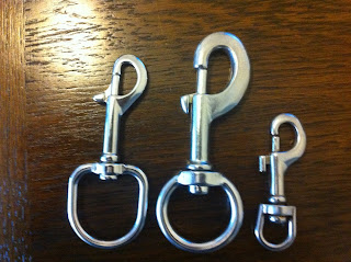
There are various types of p-clips on the market and on the right are a few of the most commonly seen. 
(From L to R) The first one is the ideal clip.  Its 1” eye means it’s easy to manipulate however the gate isn’t so large that you’ll accidently clip it to something you shouldn’t.  Although the next also has a 1” eye, the larger gate is a double edged sword.  It’s much easier to clip on than the previous clip however it’s also very easy to accidently clip it to something you shouldn’t.  Finally the last one whilst ideal for regulators, backup torches and SPGs, is very hard to manipulate and one would struggle to find the left hip D-ring.

Fold the line so that one end is approximately 9" longer.  Attach the length of cave line and use it to pull the thick line through the hose.

Pull about 20cm (8") of line through so you have enough room to attach the upper p-clip.

Attach the upper p-clip by using an overhand knot.

Place the rigging over the valve on the cylinder.  The p-clip should be positioned so it lies above the cylinders’ shoulder, on the crown.  If it's too low the bottle will cause a lot of drag once clipped to the diver.

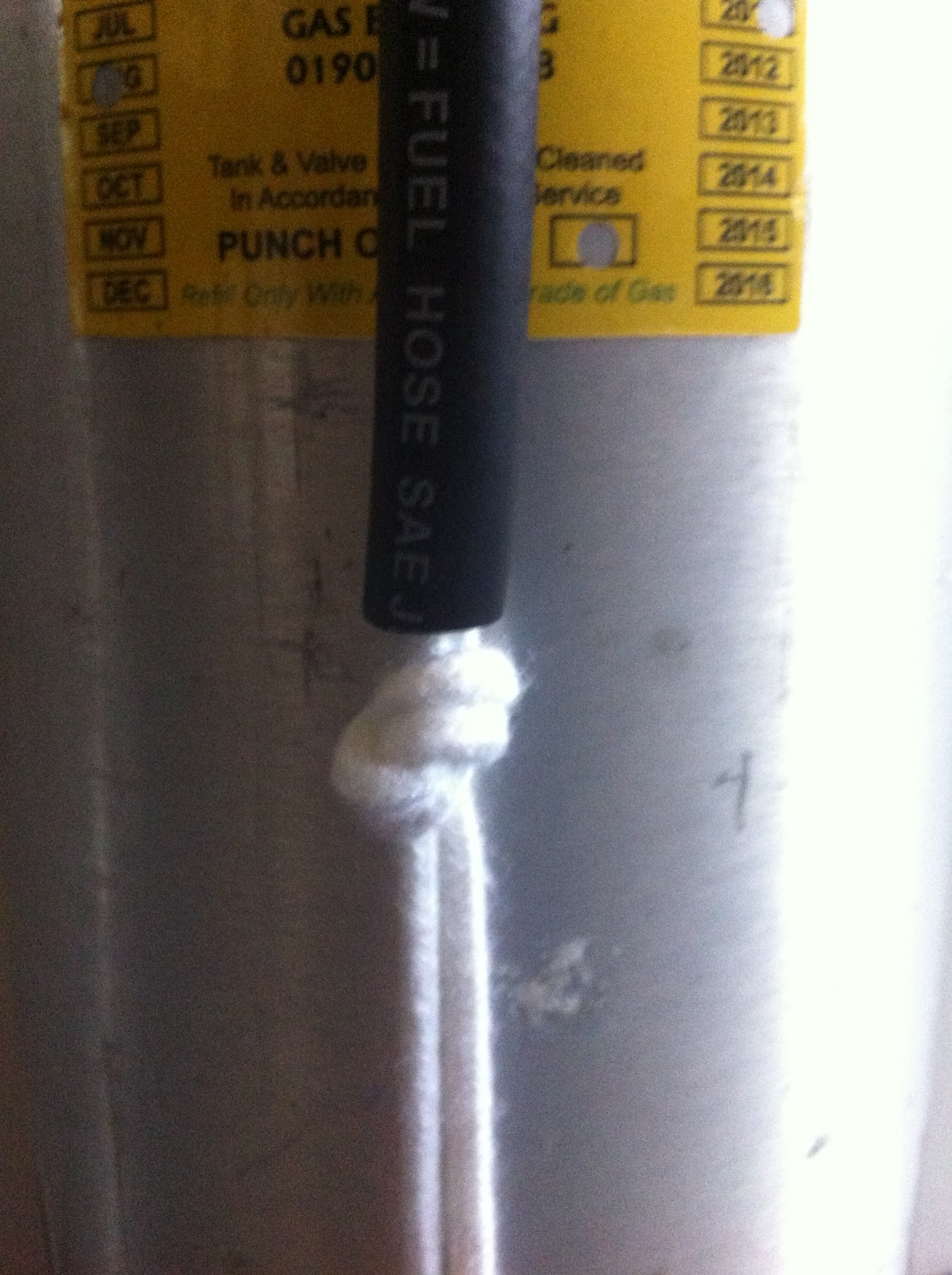
Tie an overhand knot just below the hose.  Make sure the knot is tight as possible and that’s it’s as close to the hose as possible.

   
You can attach the lower p-clip so it's either removable or permanent.  I prefer the removable method as it tends to be easier to locate.

You want 3-4" of slack on the lower p-clip.  If you want it closer you can wrap the p-clip under the handle once the rigging is finished (see below).

Now we’re going to make a fishermans knot (two overhand knots) to hold everything together.

With the longer line, tie an overhand knot approximately ½” below the knot at the base of the fuel tubing.  Be sure the shorter section of line runs through the loop of the knot before it’s tightened.  Tighten this knot as much as possible.  The ½” space is where the hose clamp will be positioned.

Tighten the second overhand knot against the prior overhand knot, creating a fisherman’s knot. 

Try to make them "fit" together and be as tight as possible.

When you are satisfied cut of the excess line and burn the ends with a lighter.

The rigging is now complete. 

Undo the jubilee clip and slide the racing bike innertube over the clamp.

Place the rigging over the cylinder as before and slide a length of car innertube over the cylinder.  This will go underneath the jubilee clip to minimize corrosion between the 2 different metals.

Place the jubilee clip on the cylinder so it fits between the knots on the bottom of the rigging. Pull down on the rigging and tighten jubilee clip as tight as possible. 

Cut off any spare clip with snips.

Finally put on the car innertube strips over the handle for regulator stowage.

As previously mentioned if you want a shorter leash, wrap it around the handle.


Well done, your stage/decompression cylinder is now rigged ready for use.  Next we need to ensure it is correctly marked and the stage/decompression regulators are set up correctly.

The boring bit!
All opinions expressed in my articles are my own and may differ to other instructor’s and agency guidelines; by no means are they wrong and I would not wish to disrepute any of them.  This article is for information only and should not replace proper training.

Safe diving!

Timothy Gort
BSAC, PADI & SDI/TDI diver training
l Mob: 07968148261 l Email: tim@rectotec.co.uk l