In my last
2 articles on stage/decompression cylinders we looked at making the rigging kit
(here) and correctly labeling the cylinder
(here).
My last looks at setting up the regulators.
Overview
This
article is written for stage/decompression cylinders which are worn on the left
side of the diver. This article is also
written using Apeks regulators. This article can be used with other
manufactures regulators however there
may be some slight differences.
Setting up
You will
need the following:
4. 6” HP hose.
5. 40” LP hose
(depending on first stage used).
6. 6”/15cm
of cave line (the stuff from your spool).
7. Lighter.
7. Lighter.
8. Scissors/knife.
Attach the
1st stage to the cylinder with the HP port facing down. Then attach the 2nd stage and hose
as follows:
(A standard
regulator hose is 29” long; too short for the regulator to be looped around
the back of the head)
*Refer to
manufacturer if unsure.
Then attach the SPG
and 6” hose. The reason a 6” HP hose is
used instead of a standard 24” is because it allows better routing. If the longer hose was used it would either
have to be clipped off somewhere, or, if stowed down the cylinder in a similar
manor to the regulators, there is a possibility of pulling it out. The other advantage a 6” hose gives is the
gauge is visible without the diver having to use a hand to get to it.
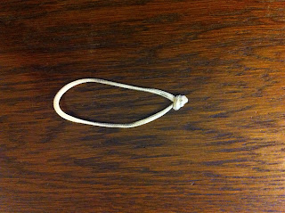
Next take the line
and tie a loop approximately 2” long. As
per the boltsnap how to (here), melt the ends with
a lighter and flattening them with the base of the lighter. This will stop the ends from fraying and
reduce the risk of the knot coming undone.
Bend the 6” hose back
on itself and place the loop over. It
should naturally sit above the ends of the hose.
Notice the hose is
protected between the 1st stage and the cylinder valve.
All that’s now left
to do is tidy up the 2nd stage hose.
This is routed along the left hand side of the rigging kit with the
mouthpiece of the 2nd stage tucked behind the hose keeping it in
place, all nice and neat.
Thank you very much for reading. Hopefully you should now have a stage/decompression cylinder looking something like mine.
The boring bit!
All opinions
expressed in my articles are my own and may differ to other instructor’s and
agency guidelines; by no means are they wrong and I would not wish to disrepute
any of them. This article is for
information only and should not replace proper training.
Safe diving!
Timothy Gort
BSAC, PADI
& SDI/TDI diver trainingl Mob: 07968148261 l Email: tim@rectotec.co.uk l


Really impressed. Please share more… Also don't forget to see this Cylinder Regulators
ReplyDelete