
Overview
A correctly
worn stage/decompression cylinder will be stable on the body and easy to
manage, especially when using more than one. Within most agencies the standard practice is
to wear the cylinders on the divers left side (due to the long hose and the
possibility of a scooter (DPV) on the right), clipped off to the left chest
D-ring and left hip D-ring. Any
cylinders not worn here are usually towed behind on a leash. When worn the cylinder (valve outlet) should
face up, the valve hand wheel should be on the left making it easy to use.
Construction
The rigging
will also be made from rope and offer no metal to metal contact so all
connections can be cut by a knife/cutter if required in an emergency. The p-clips will be made from 316 marine
grade stainless steel (not brass) with a 1” eye to aid clipping off. This is to allow one finger to maneuver the
cylinder whilst the thumb operates the gate.
Remember; despite its name, the handle is not to be used as such.as it
loosens off the rigging. The handle is
designed to lift the stowage bands away from the cylinder allowing the diver to
gain access with their finger/thumb to stow the regulator.
The
following guide will allow you to construct a kit similar to the ones I
mentioned above.

2. 2x 316
stainless steel boltsnaps (see below).
4. 180mm
316
stainless steel jubilee clip.
5. 1” strip of racing bike innertube.
6 3x 1”
strips of car innertube.
In addition
you will also need to following to assist in the making of the rigging:
1. Lighter.
2.
Scissors/knife.
3. 18” of cave line (the
stuff from your spool).
4. Screwdriver.
5. Tin snips.
 There are
various types of p-clips on the market and on the right are a few of the most
commonly seen.
There are
various types of p-clips on the market and on the right are a few of the most
commonly seen.
(From L to
R) The first one is the ideal clip. Its
1” eye means it’s easy to manipulate however the gate isn’t so large that
you’ll accidently clip it to something you shouldn’t. Although the next also has a 1” eye, the
larger gate is a double edged sword.
It’s much easier to clip on than the previous clip however it’s also very
easy to accidently clip it to something you shouldn’t. Finally the last one whilst ideal for
regulators, backup torches and SPGs, is very hard to manipulate and one would
struggle to find the left hip D-ring.

Fold the
line so that one end is approximately 9" longer. Attach the length of cave line and use it to
pull the thick line through the hose.

Pull about
20cm (8") of line through so you have enough room to attach the upper p-clip.

Attach the
upper p-clip by using an overhand knot.

Place the
rigging over the valve on the cylinder.
The p-clip should be positioned so it lies above the cylinders’
shoulder, on the crown. If it's too low
the bottle will cause a lot of drag once clipped to the diver.
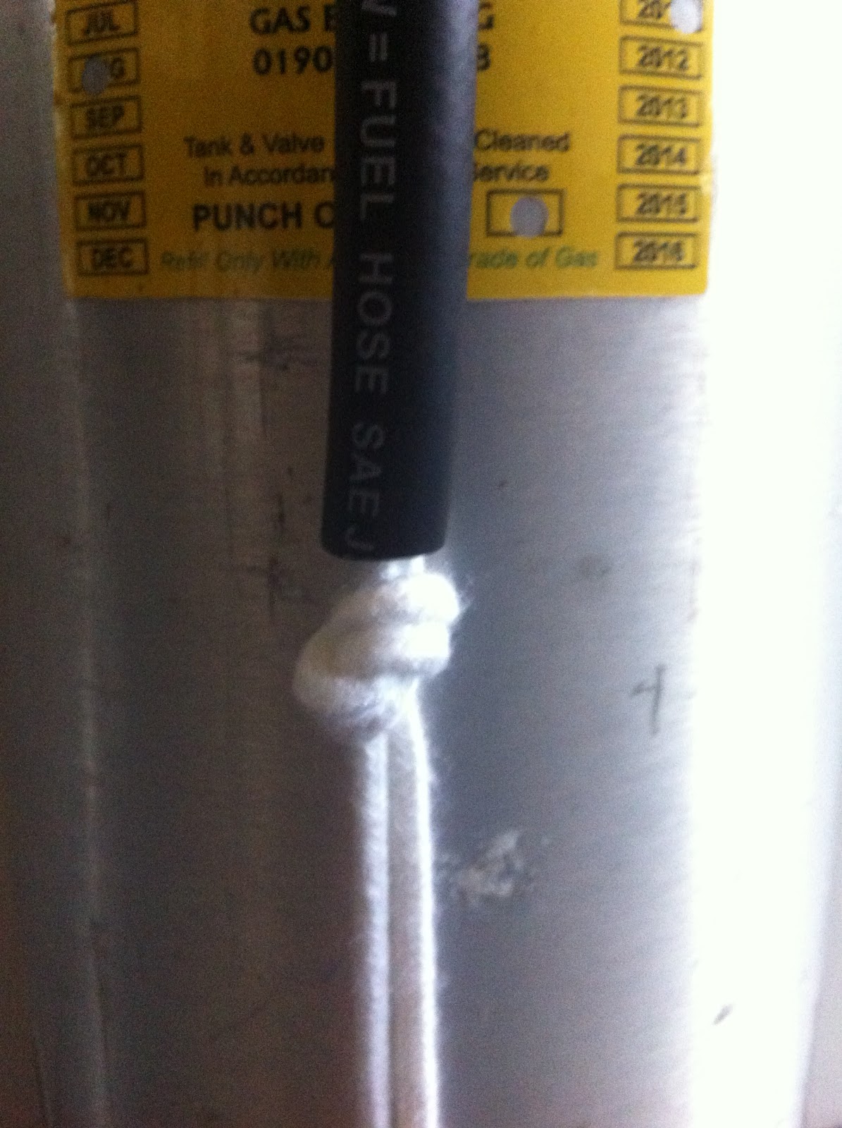
Tie an
overhand knot just below the hose. Make
sure the knot is tight as possible and that’s it’s as close to the hose as
possible.


You can
attach the lower p-clip so it's either removable or permanent. I prefer the removable method as it tends to
be easier to locate.

You want
3-4" of slack on the lower p-clip.
If you want it closer you can wrap the p-clip under the handle once the
rigging is finished (see below).

Now we’re
going to make a fishermans knot (two overhand knots) to hold everything together.
With the
longer line, tie an overhand knot approximately ½” below the knot at the base
of the fuel tubing. Be sure the shorter
section of line runs through the loop of the knot before it’s tightened. Tighten this knot as much as possible. The ½” space is where the hose clamp will be
positioned.

Tighten the
second overhand knot against the prior overhand knot, creating a fisherman’s
knot.

Try to make
them "fit" together and be as tight as possible.

When you are satisfied cut of the excess line and burn
the ends with a lighter.

The rigging
is now complete.

Undo the
jubilee clip and slide the racing bike innertube over the clamp.

Place the
rigging over the cylinder as before and slide a length of car innertube over
the cylinder. This will go underneath
the jubilee clip to minimize corrosion between the 2 different metals.

Place the jubilee
clip on the cylinder so it fits between the knots on the bottom of the rigging.
Pull down on the rigging and tighten jubilee clip as tight as possible.

Cut off any
spare clip with snips.

Finally put
on the car innertube strips over the handle for regulator stowage.

As previously
mentioned if you want a shorter leash, wrap it around the handle.
Well done, your stage/decompression cylinder is now rigged ready for use. Next we need to ensure it is correctly marked and the stage/decompression regulators are set up correctly.
The boring bit!
All opinions
expressed in my articles are my own and may differ to other instructor’s and
agency guidelines; by no means are they wrong and I would not wish to disrepute
any of them. This article is for
information only and should not replace proper training.
Safe diving!
Timothy Gort
BSAC, PADI
& SDI/TDI diver trainingl Mob: 07968148261 l Email: tim@rectotec.co.uk l

GOOD ONE ......
ReplyDeleteNice Post Your content is very inspiring and appriciating I really like it please visit my site
ReplyDeletequote status
SMS bomber
Please visit my site for kolkata fataft
check out this website young soch for some amazing business ideas and success story and also
visit this site movierulzz to download latest movies
this website more about physiotherapy will help you to learn physiotheraphy concept